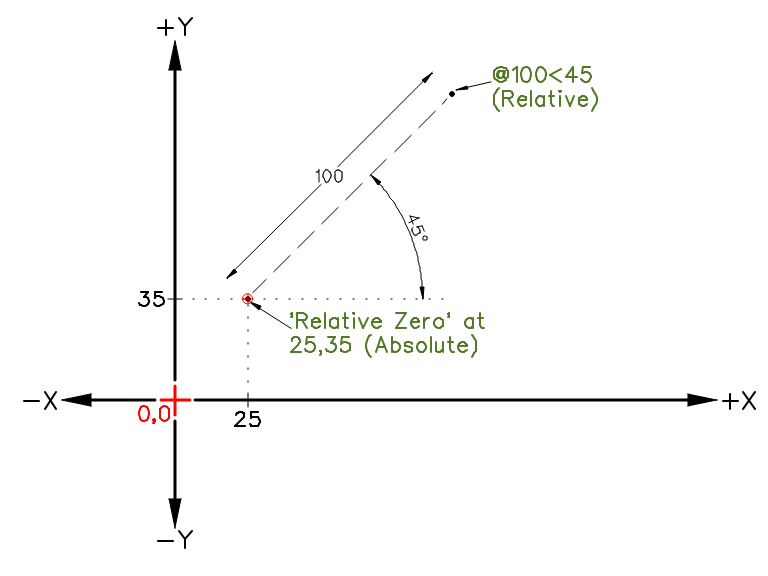


Since we have three values of the triangle we can calculate the other values with

Select the file of the freehand drawing File:CarportFreehand.jpg.To support the transition from the freehand sketch to the LibreCAD CAD drawing you can optionally insert a scanned version of your freehand drawing as an image.
Librecad commands zip file#
You'll find a saved version up to this step in the file File:CarportEastStep1.dxf or in the zip file mentioned above. You can also check what the print looks like with File/Print Preview which will open up a new tab This time if you print things out with File/Print the result should be visible. You might want to save your result with File/Save. Hint: You should type these commands to learn the process but in future you can copy/paste multiple commands using the special command action on right of command line. Should you have made a typing error you might want to use the "undo" command to remove the latest drawing item that didn't go as you intended. Select the default layer in the Layer list by clicking on itĪdd three more polylines in the default layer: Try printing the page with File/Print - the printout should be empty since the construction layer will not be printedįor the frame we would like to create three "rectangles" that represent the sides of the frame.Įach side has 40 mm width, so we simply take the three corners of the triangle:Īnd shift the coordinates by 40 mm accordingly. You should now see a 5 x 1.3 m rectangle at 1:20 scale Zoom out with the View/AutoZoom menu item Type polyline or "pl" - you'll now be asked for the points.Hit space to enter the command line mode - the cursor will jump to the command box (bottom or lower right corner) and "Command" will be in blue (you can type clear in the command box if the state of things is not like that).Note: Command Widget must be displayed (Widgets, Dock Widgets, Command Line). Since we want precise positions for this box we'll use the Command Line Mode and create a Polyline. We'd like to create a 5000 x 1300 mm construction line drawing box in which our construction will be placed. The new layer might have a name such as 'construction', and a colour of magenta or cyan or similar. Create a new Construction layer by clicking the "+" sign in the Layer list.they extend off the screen in both directions. All straight construction lines are of 'infinite' length - i.e. The first lines of any technical drawing are the construction lines, setting out the locations of all lines without specifying any line types, colours, etc. And set Landscape for the paper direction. Via the menu Options/Current Drawing Preferences/Dimensions we can set the General Scale to 20 to achieve the scaling. We'd like to have an A4 drawing on which a scaled version of the 5000 x 1300 mm construction fits.Ī4 is 297 x 210 mm so if we make the 5000 mm be shown as a 250 mm long line we'd be set. Reopen the file and close the "unnamed document 1" by clicking the circled x in the tab.The saved file "CarportEast.dxf" should show up in the "File/Recent Files" Menu Check that the save was successful by Quitting LibreCAD, and restarting it.Save the default "unnamed document 1" as "CarportEast" using the "File/Save" Menu.For this example the background color has been changed to "white".First you might want to decide about your application preferences using Options/Application Preferences/Appearance (in Version 2.0.9 Edit/Application Preferences).Check your version via the Help/About menu item - the example here have been created with version 2.1.3.

We'd like to create a drawing of the following aluminium structure which sits on top of a carport. This is quick and simple and so allows for greatest freedom in the design process. The first part of any design is a freehand sketch on paper. 6.2.2 Drawing the beams using the command line.6.2.1 Drawing the beams using the mouse.5.1 Adding the freehand sketch (optional).


 0 kommentar(er)
